
HCYY11112019 Boom Rear-Tilt Prevention Cylinder
HCYY11112019 Boom Rear-Tilt Prevention Cylinder: catalogue specifications, technical evidence, engineering interpretation, installation, maintenance, and RFQ guidance.
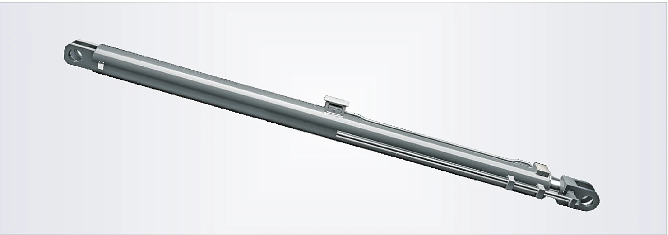
Catalogue technical data
| Field | Value | Evidence class |
|---|---|---|
| Cylinder model | HCYY11112019 | Catalogue exact |
| Catalogue name | Boom Rear-Tilt Prevention Cylinder | Catalogue exact |
| Specifications | Φ190×Φ160×1400 | Catalogue exact |
| Working pressure | 31.5 MPa | Catalogue exact |
| Maximum withstand pressure | 40 MPa | Catalogue exact |
| Travel | 1400 mm | Catalogue exact |
| Installation distance / length | 4300 mm | Catalogue exact |
| Weight | 820 kg | Catalogue exact |
| Derived: Piston area | 28,353 mm² | Derived calculation |
| Derived: Annulus area | 8,247 mm² | Derived calculation |
| Derived: Theoretical extension force at printed working pressure | 893.1 kN | Derived calculation |
| Derived: Theoretical retraction force at printed working pressure | 259.8 kN | Derived calculation |
| Derived: Theoretical full-bore oil volume for one printed travel | 39.69 L | Derived calculation |
| Derived: Rod-to-bore diameter ratio | 0.84 | Derived calculation |
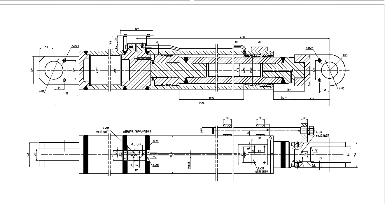
What this catalogue entry supports
HCYY11112019 is identified by the supplied catalogue as a boom rear-tilt prevention cylinder in the crawler crane cylinders group. The source supports the printed designation, model code, dimensional shorthand, pressure fields, travel, installation value, mass, product photograph, and dimension drawing reproduced above. It does not state the seal compound, tube material, rod coating thickness, port thread, valve setting, internal leakage limit, paint system, fatigue life, interchangeability, or availability. Those items must be defined by a current quotation and approved manufacturing drawing.
The most reliable way to use this page is as an RFQ starting point. A buyer can compare the printed row with the existing machine, attach photographs and measurements, and identify discrepancies before any replacement claim is made. The model number alone is insufficient because cylinders with similar bores and strokes may differ in pin width, boss offset, port orientation, tube-wall design, cushioning, valve blocks, sensor interfaces, and closed-length definition.
Engineering interpretation of Φ190×Φ160×1400
The catalogue notation is reproduced exactly as Φ190×Φ160×1400. For this page, the first diameter is treated as the cylinder bore, the second as the piston-rod diameter, and the final figure as the nominal travel only where the source layout clearly supports that reading. This interpretation is useful for preliminary calculations, but it is not a substitute for the sectional drawing. Production control should remain with an approved drawing that defines tolerances, datum points, seal grooves, weld details, ports, pin fits, and inspection criteria.
Using the printed working-pressure value, the preliminary calculation set gives piston area 28,353 mm², annulus area 8,247 mm², theoretical extension force at printed working pressure 893.1 kN, theoretical retraction force at printed working pressure 259.8 kN, theoretical full-bore oil volume for one printed travel 39.69 L, rod-to-bore diameter ratio 0.84. These are ideal hydraulic values before friction, pressure loss, efficiency, linkage ratio, gravity, acceleration, shock, and safety factors. They should never be treated as guaranteed machine output. The maximum withstand-pressure field is also not an invitation to operate continuously at that pressure; it is a separate catalogue entry whose test meaning and duration need confirmation.
Application duty and load path
Crawler-crane cylinders carry very high structural loads and interact with boom, mast, counterweight, frame, and safety systems. The catalogue values are useful evidence, but the approved machine calculation and drawing remain controlling documents.
For HCYY11112019, the load path should be traced from the pressure acting on the piston through the rod, gland, tube, end closures, mounts, pins, bushes, weldments, and machine structure. A cylinder can be hydraulically adequate yet fail prematurely when the linkage bends the rod, the pin bosses are not coplanar, the mount cannot rotate freely, or the external stops allow the piston to absorb impact. The review should include both normal operating positions and exceptional conditions such as transport vibration, blocked motion, emergency lowering, overload, and maintenance handling.
Geometry, mounting, and buckling review
Confirm load cases, boom configuration, reeving, dynamic factors, buckling margin, bearing pressure, pin material, weld load path, support sequence, transport condition, safety valve arrangement, and the effect of chassis deflection on alignment.
The printed installation value for this model is 4300 mm, but the catalogue does not define the exact measurement datums in the text row. Use the drawing to identify whether it represents pin centre to pin centre, a flange reference, an overall closed length, or another datum. Measure the machine in the same state and with the same datum definition. Check pin diameter, usable pin length, boss width, spherical-bearing freedom, clevis gap, trunnion location, flange pilot, clocking, and the possibility of assembly without forcing the structure.
Compression-loaded rods need a buckling review based on unsupported length, end conditions, rod material, diameter, straightness, load eccentricity, and dynamic amplification. A simple stroke-to-rod ratio is not enough. Long travel, a small rod, or a heavy attachment should trigger a detailed calculation and a review of guides or linkage support. Tension-loaded cylinders still need thread, weld, eye, and pin checks, and double-rod steering designs require alignment on both ends.
Hydraulic circuit, ports, and load control
The catalogue gives pressure but not flow. Required speed therefore cannot be confirmed without the machine cycle time and available pump flow. The buyer should provide target extension and retraction times, pump displacement or measured flow, relief setting, return pressure, fluid type, viscosity range, filtration level, reservoir temperature, and the existing port standard. A mismatch between SAE, BSPP, metric, flange, or custom ports can create unsafe adapters, restricted flow, or hose interference.
Load-holding and motion-control requirements must be established from the application. Boom, platform, grain-tank, support, or suspended-load functions may require counterbalance, pilot-operated check, hose-burst, over-centre, sequencing, or lock valves. The catalogue photographs do not prove that a valve is included. Valve location, cracking or pilot ratio, thermal relief, emergency lowering, pressure intensification, and trapped-volume behavior all require circuit review. Cushioning is also not stated, so end-of-stroke deceleration should be handled by confirmed internal cushions, external controls, or machine stops rather than assumed.
Brazil operating environment
Crawler cranes in Brazilian construction, mining, ports, energy, and infrastructure projects may work in high heat, rain, abrasive dust, and remote locations. Inspection access, corrosion protection, and contamination management should be planned before commissioning.
Environmental specifications should be written into the RFQ rather than left as general expectations. State indoor or outdoor use, temperature range, humidity, salt or chemical exposure, abrasive dust, mud, washing method, storage duration, ultraviolet exposure, and desired coating system. Identify whether the rod is normally retracted during storage and whether debris can accumulate near the wiper. For agricultural and mobile fleets, also describe seasonal idle periods and the availability of clean hydraulic oil, filtration, and trained maintenance personnel.
Installation and commissioning workflow
- Compare the catalogue drawing with the machine assembly and record every interface dimension, port, valve, and sensor.
- Inspect pins, bushes, brackets, and structural alignment before installing a new cylinder; do not use the cylinder to pull misaligned lugs into position.
- Flush or cap open hoses, confirm fluid compatibility, lubricate pins correctly, and protect the rod from welding spatter or handling damage.
- Bleed air using the machine procedure, begin at low pressure and low speed, and watch for binding, hose twist, abnormal noise, or pressure spikes.
- Cycle through the complete motion envelope without load where the machine design permits, then introduce load progressively while monitoring temperature and leakage.
- Record final pin retention, hose clearance, valve settings, test results, and the approved drawing revision in the maintenance file.
Maintenance and troubleshooting
Routine inspection should look for rod scoring, corrosion, chrome damage, wiper displacement, external leakage, loose pins, elongated holes, cracked welds, tube dents, hose abrasion, and changes in operating speed or drift. Clean the rod before long storage and correct the source of contamination rather than repeatedly replacing seals. A leaking rod seal may be caused by damaged surface finish, side load, pressure spikes, incompatible fluid, heat, or contaminated oil, not only by seal wear.
Slow motion can result from restricted flow, aeration, pump wear, valve problems, internal bypass, mechanical binding, or cold high-viscosity oil. Drift may originate in the cylinder, control valve, load-holding valve, or external plumbing. Isolate the fault with an approved test procedure rather than tightening the relief valve. Repeated end-cap, eye, or rod failures usually indicate overload, impact, misalignment, or inadequate structure and should trigger a system-level investigation.
RFQ and drawing-approval checklist
- Model code HCYY11112019, catalogue page 26, and a copy of the existing nameplate or drawing.
- Machine manufacturer, model, serial number, function, and working environment.
- Bore, rod, travel, closed and open dimensions, installation datums, pin sizes, boss widths, and mount type.
- Port thread or flange, port orientation, tube routing, valve block, test ports, sensors, and hose-clearance envelope.
- Working pressure, relief setting, transient pressure, flow, required speed, duty cycle, load direction, and load-holding requirement.
- Materials, rod surface, seals, paint or coating, corrosion target, cleanliness, testing, documentation, marking, and packing.
- Quantity, annual demand, requested samples, drawing format, inspection plan, and approval responsibilities.
Evidence boundary
This page separates catalogue facts from calculations and engineering interpretation. The specification table and drawing are source-derived. The force and volume figures are mathematical estimates based on the printed bore, rod, travel, and working pressure. The installation, circuit, environment, and maintenance sections describe questions that should be resolved; they do not assert hidden construction details. No price, stock, certification, customer approval, OEM interchange, guaranteed life, local warehouse, or delivery time is claimed.
Frequently asked questions
Is HCYY11112019 a direct replacement for a specific machine?
No direct replacement is claimed. Confirm the machine model, complete interface geometry, ports, valve arrangement, pressure, load path, and approved drawing before purchase.
Can the printed withstand pressure be used as the normal operating pressure?
No. The catalogue lists working and maximum withstand pressure separately. Continuous operation, proof-test method, and transient limits must be confirmed by the manufacturer and project documents.
Does the page confirm seal material or rod coating?
No. Seal compound, wiper design, rod material, surface treatment, hardness, roughness, and coating thickness are not stated in the product row and must be specified for the application.
What information is most important for a Brazil RFQ?
Provide the machine identity, crop or industrial duty, temperature, dust, moisture, chemical exposure, port standard, measurements, photographs, pressure, flow, cycle time, quantity, and required documentation.
Why is drawing approval still required after automatic website publication?
Website publication confirms that the page is supported by the catalogue. Drawing approval is a separate manufacturing and compatibility control that defines the exact ordered configuration.
Send the machine data for HCYY11112019
Attach the existing drawing, photos, measurements, port details, pressure, flow, duty cycle, environment, quantity, and documentation requirements.