
FORWARD STACKER Forward Stacker Hydraulic Power Unit
FORWARD STACKER Forward Stacker Hydraulic Power Unit: catalogue specifications, technical evidence, engineering interpretation, installation, maintenance, and RFQ guidance.
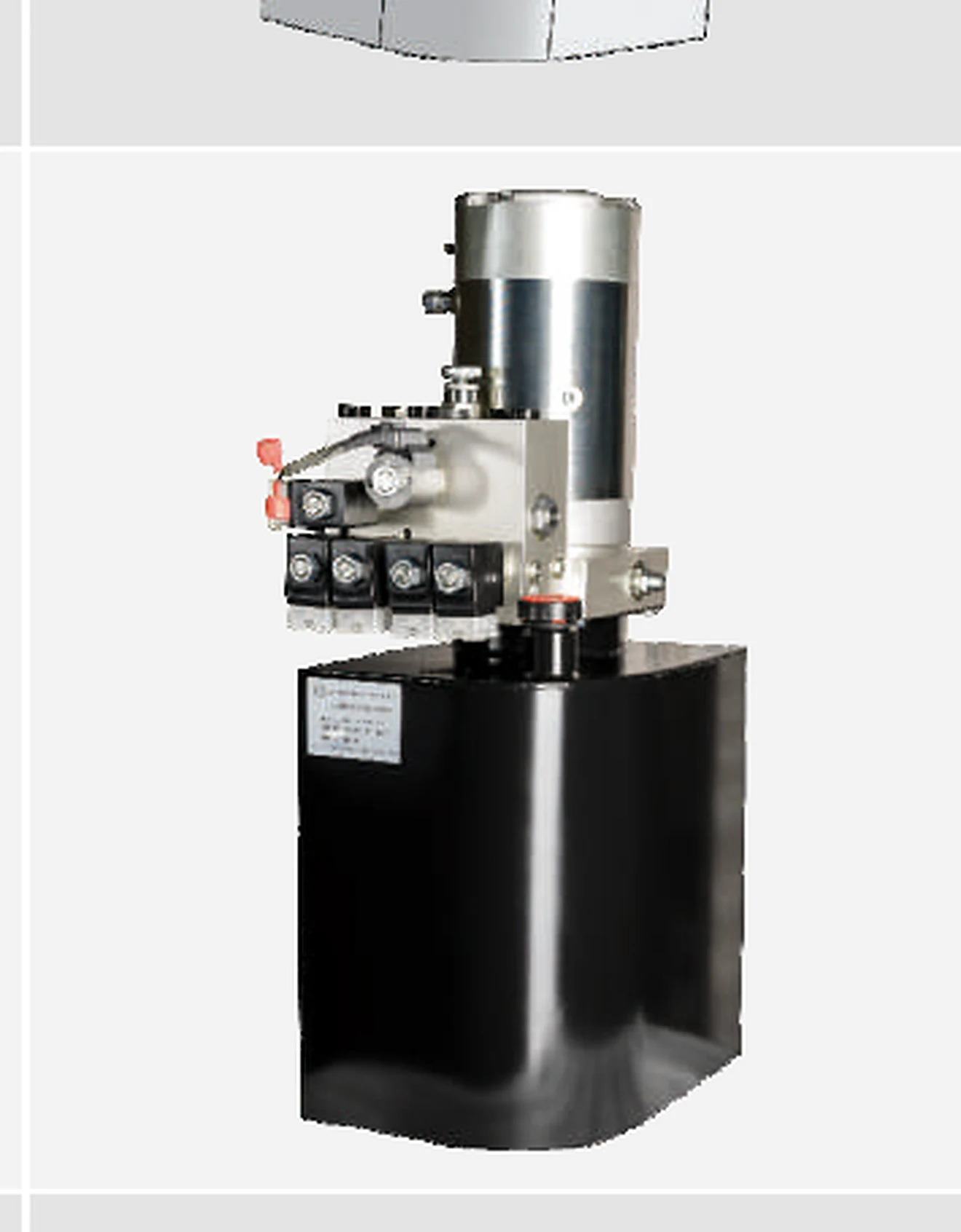
Catalogue technical data
| Field | Value | Evidence class |
|---|---|---|
| Catalogue designation | FORWARD STACKER | Catalogue exact |
| Product name | Forward Stacker Hydraulic Power Unit | Catalogue exact |
| Source page | 33 | Catalogue exact |
| DC voltage | 24.0 V | Catalogue exact |
| Motor power | 3.0 kW | Catalogue exact |
| Rated speed | 2850 r/min | Catalogue exact |
| Pump displacement | 3.7 ml/r | Catalogue exact |
| Noise | ≤70 dB | Catalogue exact |
| Overflow valve | 20.5 MPa | Catalogue exact |
| Electromagnetic valve | Proportional electromagnetic valve | Catalogue exact |
| Throttle valve | 15 L/min | Catalogue exact |
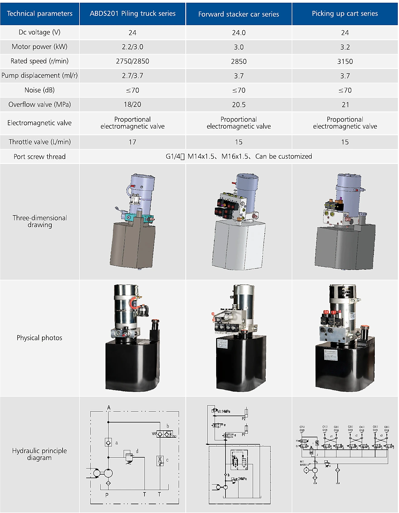
Series purpose and source boundary
Forward Stacker Hydraulic Power Unit is one of six compact power-unit series compared on catalogue page 33. The page supports the printed electrical supply, motor power, motor speed, pump displacement, noise entry, overflow-valve pressure, electromagnetic-valve type, throttle-flow value, product image, and typical hydraulic principle. It does not define reservoir volume, complete dimensions, duty classification, motor insulation, ingress protection, fluid, filtration, wiring connector, solenoid voltage tolerance, thermal limits, or a final customer circuit.
The series should therefore be selected by matching the complete machine cycle, not by choosing only the nearest motor power. A compact hydraulic power unit is a system that combines electric motor, pump, reservoir, valve block, relief or overflow protection, return path, and optional control valves. Small changes in cylinder area, load, travel, cycle time, or lowering method can change the required flow, pressure, reservoir, motor duty, heat balance, and valve arrangement.
Electrical and hydraulic data
The catalogue prints 24.0 V DC supply, 3.0 kW motor power, 2850 r/min rated speed, and 3.7 ml/r pump displacement for this series. These values allow a preliminary estimate of theoretical pump flow, but the real flow depends on motor speed under load, pump volumetric efficiency, fluid viscosity, wear, temperature, and pressure. Battery voltage also changes during discharge and high-current operation.
The overflow-valve entry is 20.5 MPa. This is a catalogue setting or range, not a universal machine relief setting. The selected pressure must remain within the cylinder, hose, fitting, valve, structure, and motor-power limits. It must also provide sufficient force after accounting for friction and pressure loss. A higher setting can increase heat and electrical current and may overload the machine even when the power unit itself survives.
Flow, speed, and cycle calculation
Use the cylinder bore, rod, and travel to calculate oil volume for each motion. Divide volume by the required time to obtain the necessary delivered flow, then add realistic efficiency and leakage allowances. For multiple actuators, define whether motions are simultaneous or sequential. Lowering flow may be controlled by gravity, a throttle, a proportional valve, or a powered reverse circuit; each arrangement has different heat, stability, and safety implications.
The printed throttle value for this series is 15 L/min. It should not be treated automatically as cylinder speed. The actual circuit diagram, valve orifice, load, pressure differential, and cylinder area determine motion. For a pallet truck or stacker, lowering stability with different loads can be more important than maximum lifting speed. For a piling or picking machine, proportional response and repeatability may be more important.
Motor, battery, cable, and control integration
Confirm the battery or DC-bus voltage, minimum voltage during cranking or lifting, peak current, cable length, conductor size, fuse or breaker, contactor, connector, grounding, control logic, and emergency stop. Motor nameplate current and duty are needed to size the electrical system. A 24 V motor can draw approximately twice the current of a 48 V motor for comparable power, so voltage choice affects cable, connector, contactor, and battery requirements.
The catalogue does not state motor duty class or thermal protection. Provide the complete cycle: starts per hour, lift duration, lowering duration, pressure during each phase, idle time, ambient temperature, enclosure, and expected consecutive cycles. The motor and oil can overheat even when each individual movement seems short. Control engineers should also define solenoid current, suppression, connector pinout, manual override, proportional-driver requirements, and fault behavior.
Valve block and hydraulic safety
The valve entry for this series is Proportional electromagnetic valve. The final manifold may require directional, check, load-holding, lowering, pressure-compensated flow, proportional, emergency manual, or sequencing functions. Page 32 notes that many hydraulic-circuit combinations can be developed, but that general capability does not prove that a particular valve is included in this series image.
For lifting equipment, define what happens after hose failure, electrical failure, valve failure, overload, or emergency stop. A load should not descend simply because the pump stops unless the machine design explicitly allows and controls that behavior. Check valve leakage, manual-lowering access, relief location, thermal expansion of trapped oil, pressure at the cylinder, and whether the reservoir can accept returning volume without overflow or aeration.
Reservoir, fluid, filtration, and thermal design
Reservoir size is not printed in the comparison table. It must accommodate usable volume, cylinder differential volume, thermal expansion, foaming margin, and machine orientation. The suction path should avoid vortexing and air ingestion. Return oil should not discharge directly into the pump inlet. A breather, filler, strainer, filter, level indication, and drain strategy should be selected for the contamination risk and maintenance practice.
State the hydraulic fluid, viscosity range, minimum start temperature, maximum operating temperature, seal compatibility, and cleanliness target. Brazilian operation can involve high ambient heat, humidity, dust, fertilizer, mud, road vibration, or warehouse washdown. A compact reservoir has limited heat-rejection area, so actual cycle testing is important. High noise, foamy oil, slow movement, or current rise can indicate aeration, cavitation, restriction, contamination, or excessive pressure.
Mechanical packaging and installation
Request an approved outline drawing showing reservoir orientation, fill level, motor clearance, valve-block ports, mounting holes, connector envelope, service access, and the permitted installation angles. The catalogue image is not dimensioned. Ensure that the power unit can be filled, bled, inspected, and removed without dismantling major machine structure. Protect the motor and valves from impact, water jets, debris, and heat sources.
Port thread is shown at family level as G1/4, M14×1.5, M16×1.5, with customization noted. Confirm the exact port on the ordered unit and do not assume every series uses every option. Minimize restrictive adapters and hose bends. Support hoses so vibration is not transferred into the valve block. Where the unit travels on a vehicle, check reservoir venting and oil level across slopes, acceleration, and transport shock.
Commissioning and acceptance test
- Verify model, voltage, polarity, motor and solenoid wiring, fuse, cable, port, fluid, reservoir fill, valve schematic, and relief setting.
- Prime according to the supplier procedure and prevent dry pump operation.
- Run at no load or reduced load where safe, confirm motor direction, pressure, flow, noise, current, leakage, and stable return flow.
- Cycle the complete machine progressively and record lift time, lower time, peak pressure, current, voltage drop, oil temperature, and reservoir level.
- Test overload protection, emergency stop, manual lowering, power-loss behavior, and load holding using the machine safety procedure.
- Recheck fittings, mounting, electrical connections, oil condition, and settings after the initial operating period.
Maintenance and troubleshooting
Inspect oil level and condition, external leakage, loose electrical connections, damaged cables, corroded terminals, clogged breathers, unusual noise, overheating, pressure drift, slow movement, and unstable lowering. A slow lift may be caused by low battery voltage, undersized cables, motor wear, pump wear, suction restriction, air, relief leakage, valve leakage, cold oil, or excessive load. Measuring voltage at the motor while lifting is often more useful than measuring an unloaded battery.
Do not raise relief pressure to compensate for low flow or a weak electrical supply. Separate pressure, flow, current, voltage, temperature, and mechanical-load checks. If the unit is replaced, compare the complete schematic and valve logic, not only the motor and reservoir appearance. A visually similar power pack can have a different normally open or normally closed valve, relief setting, lowering orifice, check valve, or port arrangement.
RFQ checklist
- Series name, machine type, quantity, annual demand, operating voltage, battery type, and minimum loaded voltage.
- Cylinder bore, rod, travel, load, lift time, lower time, simultaneous motions, starts per hour, and ambient temperature.
- Required pressure, flow, reservoir volume, fluid, filtration, breather, installation orientation, and port standard.
- Full valve schematic, normal valve states, load holding, emergency lowering, proportional control, manual override, and solenoid details.
- Motor duty, current, protection, connector, cable, fuse, noise target, testing, marking, documentation, and packing.
Evidence boundary
The table and technical image above are catalogue-derived. The system-design discussion identifies decisions that remain open. No price, stock, certification, guaranteed duty, machine compatibility, local warehouse, delivery time, or customer approval is claimed.
Frequently asked questions
Can pump flow be calculated directly from displacement and rated speed?
A theoretical value can be estimated, but delivered flow is lower and varies with pressure, efficiency, fluid, temperature, voltage, and motor speed under load.
Is the overflow-valve value the correct machine relief setting?
Not automatically. The final setting must satisfy the load while protecting every component and the machine structure.
Does the catalogue specify reservoir capacity?
No reservoir capacity is printed in the series comparison table. Request an outline drawing and volume data.
Can one power unit operate several cylinders?
Potentially, but the circuit, simultaneous demand, sequencing, return volume, valve block, heat, and safety functions must be engineered.
Why is automatic publication different from product approval?
Automatic publication confirms the catalogue evidence is displayed. The order still requires an approved circuit, outline drawing, and technical specification.
Send the machine data for FORWARD STACKER
Attach the existing drawing, photos, measurements, port details, pressure, flow, duty cycle, environment, quantity, and documentation requirements.