
CATALOGUE-FAMILY Hydraulic Direction Cylinder
CATALOGUE-FAMILY Hydraulic Direction Cylinder: catalogue specifications, technical evidence, engineering interpretation, installation, maintenance, and RFQ guidance.
Catalogue technical data
| Field | Value | Evidence class |
|---|---|---|
| Catalogue designation | CATALOGUE-FAMILY | Catalogue exact |
| Product name | Hydraulic Direction Cylinder | Catalogue exact |
| Source page | 32 | Catalogue exact |
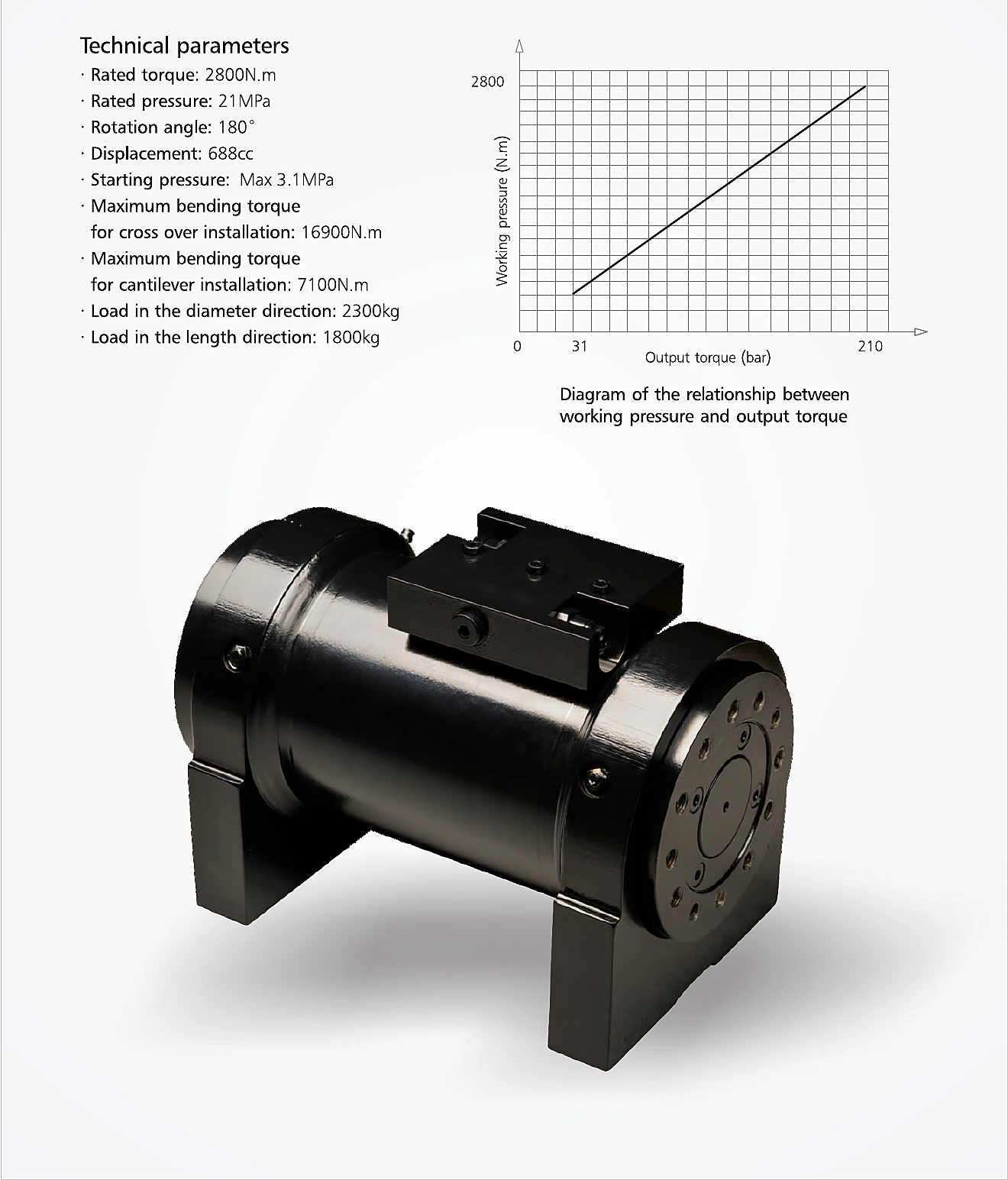
| Rated torque | 2800 N·m | Catalogue exact |
| Rated pressure | 21 MPa | Catalogue exact |
| Rotation angle | 180° | Catalogue exact |
| Displacement | 688 cc | Catalogue exact |
| Starting pressure | Max. 3.1 MPa | Catalogue exact |
| Maximum bending torque - cross installation | 16,900 N·m | Catalogue exact |
| Maximum bending torque - cantilever installation | 7,100 N·m | Catalogue exact |
| Load in diameter direction | 2,300 kg | Catalogue exact |
| Load in length direction | 1,800 kg | Catalogue exact |
How to interpret this rotary hydraulic device
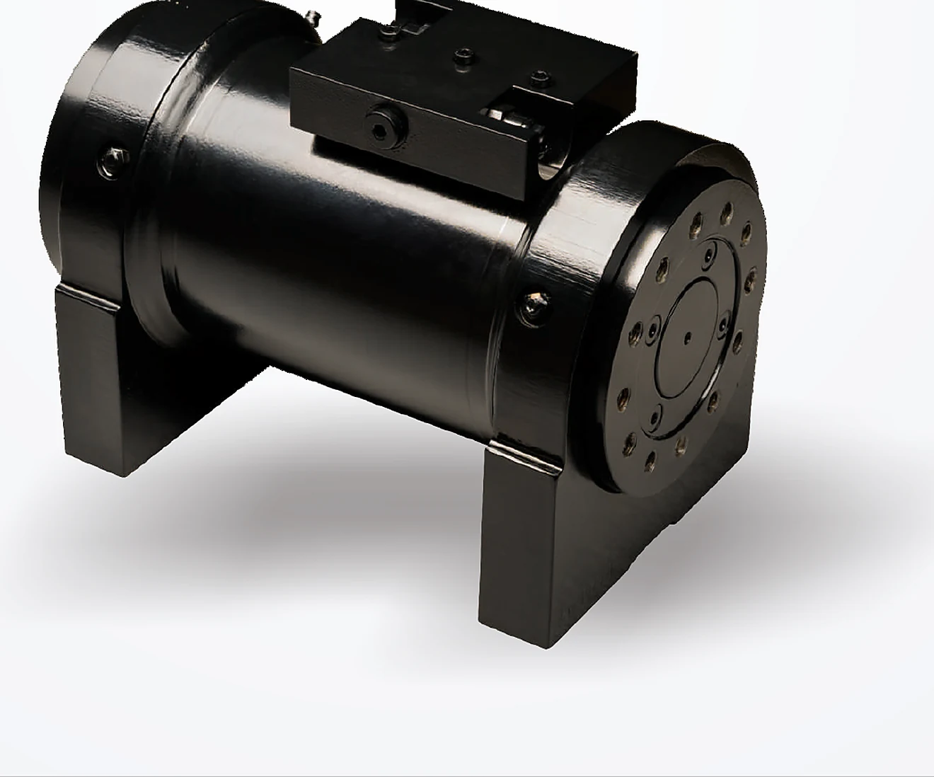
The catalogue presents this product as a hydraulic direction cylinder and gives torque, pressure, angular travel, displacement, starting pressure, bending-torque limits, and directional load values. Unlike a conventional linear cylinder, its primary output is rotary motion. The page does not print a model code, port specification, mounting bolt pattern, shaft interface, materials, seal system, backlash, rotational accuracy, or duty classification, so it should be treated as a family-level technical reference rather than a ready-to-order standard unit.
The stated rated torque is 2,800 N·m at a rated pressure of 21 MPa, with 180° rotation and 688 cc displacement. The graph on the catalogue page shows a near-linear relationship between working pressure and output torque. That relationship is useful for preliminary sizing, but actual output depends on mechanical efficiency, starting friction, oil temperature, pressure loss, and the permitted duty cycle. A project calculation should also include the attached mass, inertia, acceleration, stopping behavior, external moment, and the consequences of a blocked or uncontrolled rotation.
Mounting and bending-load review
The catalogue distinguishes maximum bending torque for cross installation and cantilever installation. This is an important warning that mounting arrangement affects allowable external loading. Cross installation is listed at 16,900 N·m, while cantilever installation is listed at 7,100 N·m. These figures should not be generalized to an unverified bracket. The actual base stiffness, bolt pattern, fastener preload, contact surface, shaft support, load offset, and dynamic factor must be reviewed together.
The page also lists 2,300 kg in the diameter direction and 1,800 kg in the length direction. The wording is preserved from the source. Before design release, ask for the supplier drawing that defines the load axes, reference point, test method, safety factor, and whether the values are static, dynamic, or proof limits. A mass value without a lever arm cannot fully define a bending moment. The machine structure and bearings must prevent unintended housing distortion or shaft misalignment.
Hydraulic circuit and control behavior
Rotary actuators may be used for steering, indexing, positioning, clamping, or directional control, but the catalogue page does not identify the final machine. The circuit designer should define target angular speed, acceleration and deceleration, stop accuracy, permissible backlash, load direction, over-running load behavior, and fail-safe position. Flow controls, cross-port relief valves, counterbalance valves, pilot-operated checks, accumulators, or proportional valves may be needed depending on the duty.
Because displacement is stated as 688 cc, angular speed can be estimated only after the actual flow and volumetric efficiency are known. Pressure spikes can occur when a rotating mass reaches the mechanical stop, when a directional valve closes rapidly, or when the external load drives the actuator. The approved design should show how energy is absorbed. Do not assume the actuator can be used as the sole mechanical stop or safety lock unless that function is explicitly designed and verified.
Fluid, cleanliness, temperature, and Brazil service
Hydraulic cleanliness is especially important in rotary mechanisms with close internal clearances. The RFQ should state the fluid type, viscosity range, minimum and maximum temperature, filtration target, reservoir design, contamination sources, and flushing method. Outdoor Brazilian applications may combine heat, high humidity, rainfall, dust, mud, salt, fertilizer, or industrial washdown. Storage and transport conditions can be as significant as operating conditions when ports or shafts are exposed.
External corrosion protection, shaft sealing, breathers, paint, fasteners, and mounting surfaces should be specified for the actual location. For mobile machinery, include vibration and shock. For stationary industrial equipment, include foundation stiffness and alignment. For agricultural or mining equipment, include abrasive contamination and remote maintenance. No coating or seal compound is stated on the catalogue page, so these choices remain open engineering items.
Design verification and acceptance criteria
A complete technical specification should convert each catalogue value into an acceptance item. Rated torque needs a defined pressure, oil temperature, rotational speed, direction, and permissible deviation. Rotation angle needs end-position tolerances and a statement of whether the internal mechanism or the external machine provides the stop. Starting pressure should be checked in both directions after temperature stabilization. External-load capability needs the axis, offset, fixture, load duration, and allowable deformation. Leakage acceptance should distinguish external leakage from internal bypass and should state the measurement period.
The supplier drawing should identify the pressure ports, drain requirement if any, shaft datum, mounting pilot, bolt size and grade, rotation direction, backlash or lost motion, mass, centre of gravity, lifting points, surface protection, and nameplate. The project inspection plan can then include dimensional verification, low-pressure function, rated-pressure torque, proof-pressure test, angular travel, holding or drift, leakage, and final cleanliness. Any requirement not supported by the catalogue should be negotiated rather than inferred.
Commissioning plan
- Verify mounting faces, bolt pattern, shaft or coupling interface, load axes, and the 180° required motion against an approved drawing.
- Flush and connect the circuit with confirmed port types; provide pressure gauges at useful diagnostic points.
- Begin at reduced pressure and flow, rotate without external load where safe, and confirm direction, smoothness, leakage, and stop position.
- Add load progressively while monitoring pressure, temperature, structural deflection, noise, and repeatability.
- Verify emergency, fail-safe, and power-loss behavior before normal operation.
- Record valve settings, test data, fastener torque, fluid condition, and the final drawing revision.
Maintenance and fault isolation
Inspect for external leakage, mounting movement, bolt relaxation, shaft or coupling wear, abnormal backlash, corrosion, temperature rise, and changes in pressure required to start motion. A higher starting pressure may indicate contamination, seal damage, internal wear, misalignment, cold oil, or an external mechanism that has become tight. Oscillation or overshoot may result from valve tuning, trapped air, flexible hoses, structural compliance, or an over-running load.
Do not adjust relief or control settings to hide a mechanical problem. Isolate the actuator from the driven mechanism using an approved procedure, compare no-load and loaded pressure, verify flow, inspect the coupling and bearings, and check whether the external load acts through the intended axis. Any repair should preserve internal timing, sealing surfaces, clearances, and test requirements defined by the manufacturer.
RFQ checklist
- Required torque across the full 180° motion, load inertia, lever arm, and dynamic factors.
- Mounting orientation, cross or cantilever arrangement, bolt pattern, shaft interface, and support bearings.
- Pressure, flow, cycle time, duty cycle, stop accuracy, allowable backlash, and fail-safe state.
- Port standard, valve strategy, cushioning or deceleration, filtration, fluid, and temperature.
- Environmental exposure, coating, sealing, corrosion target, inspection, testing, documentation, quantity, and drawing format.
Evidence boundary
All numeric values in the table above are transcribed from catalogue page 32. The application, control, installation, and maintenance discussion is engineering guidance, not a claim about unprinted features. No stock, price, certification, local warehouse, machine compatibility, or service life is stated.
Frequently asked questions
Does the catalogue provide an orderable model number?
No individual model number is visible on the page. Request a current supplier drawing and commercial designation.
Is 2,800 N·m guaranteed at every operating condition?
It is the printed rated torque. Actual output and allowable duty require confirmation of pressure, efficiency, temperature, speed, and test conditions.
Can the actuator carry cantilever load?
The source prints a cantilever bending-torque value, but the axis, reference point, bracket, and dynamic conditions must be defined on an approved drawing.
What controls angular speed?
Available flow, displacement, efficiency, load, valve characteristics, and pressure losses determine angular speed. The catalogue does not state a speed range.
Send the machine data for CATALOGUE-FAMILY
Attach the existing drawing, photos, measurements, port details, pressure, flow, duty cycle, environment, quantity, and documentation requirements.